Basic Maintenance Appliction
In case the laser spot are hard to detect, please try to use an piece of Si wafer for higher contrast or increase the power of the laser for calibration test.
To adjust the power, you need Supervisor or Service level
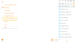
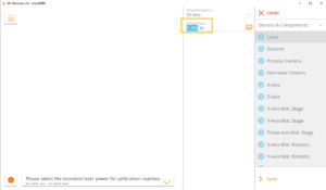
And please adjust the power setting
The Camera Laser Offset Adjustment should be carried out on a daily basis. It aligns the camera image and the overlays to each other. This enables accurate and reliable work.
First of all you should place a piece of silicon on a stub and on either the manual, motorized or the thinning stage.
Next you navigate in the software to the general settings menu and there you click on the “Camera Laser Offset” button.
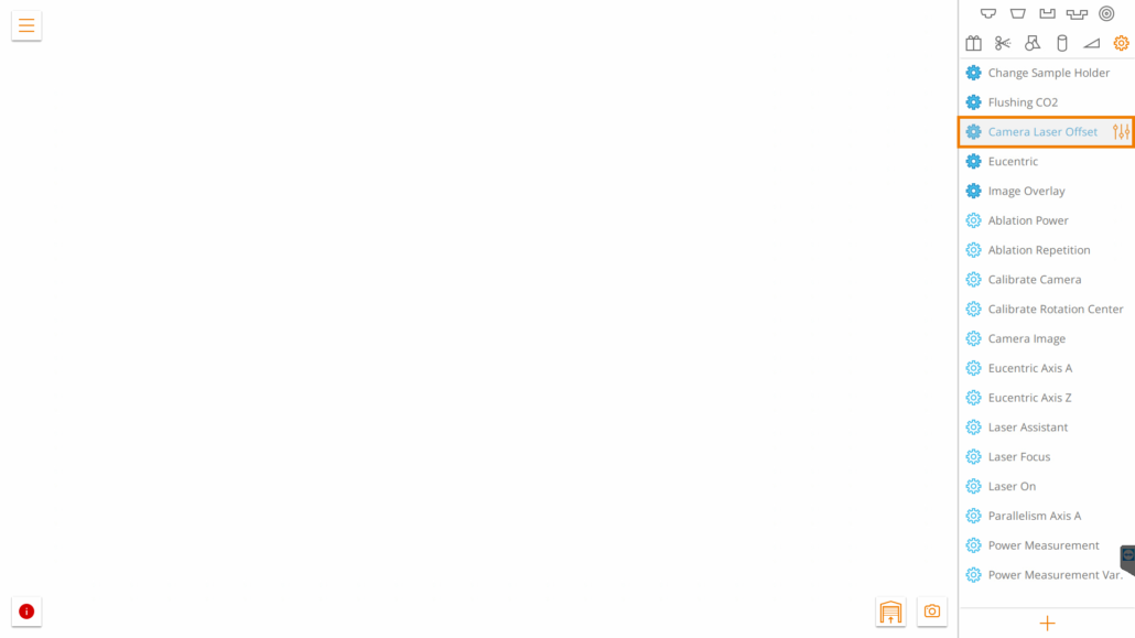
Now you will see the cross and the process camera view. You can start the calibration with the according button.
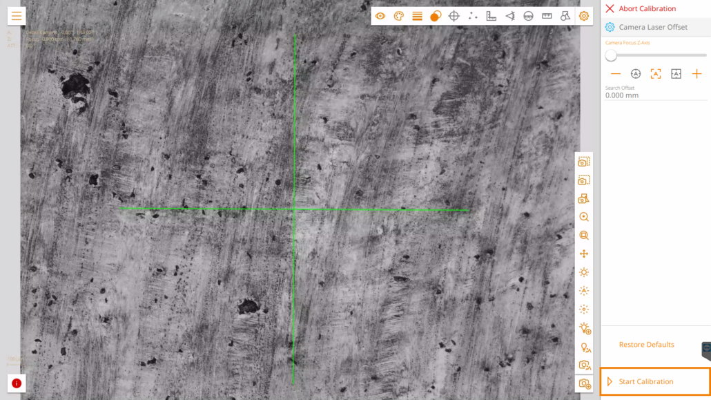
The cross will be lasered automatically and you will be directed to the next screen.
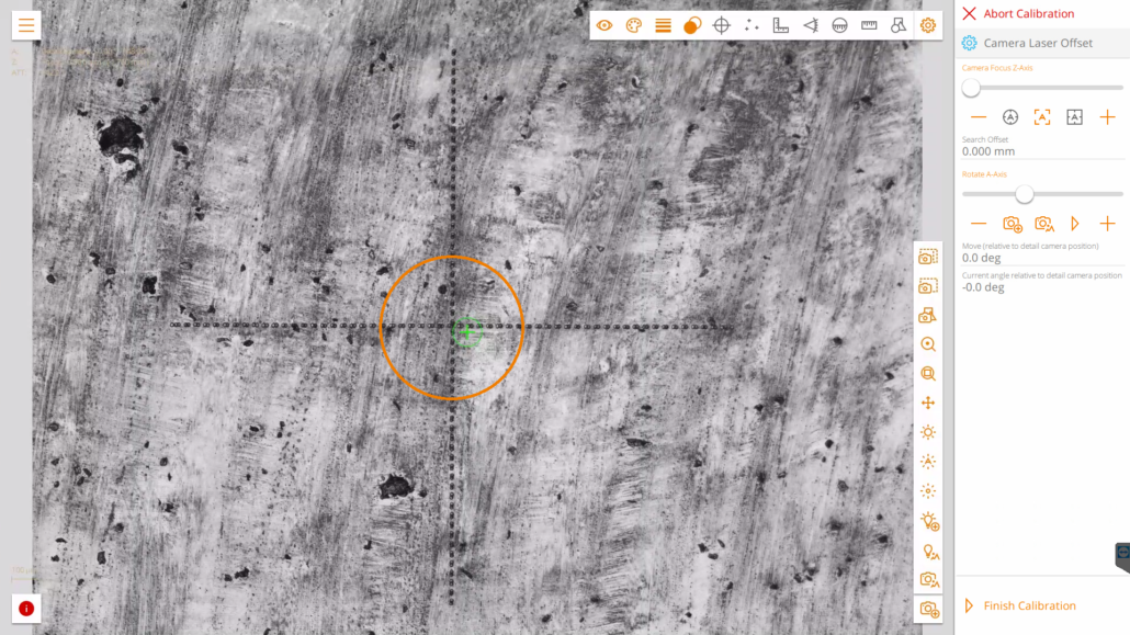
Now it is your task to place the overlay (in this picture the green crosshair) either with the mouse or the touchscreen precisely in the middle of the lasered cross.
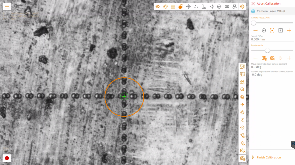
To finish the adjustment just click on “Finish Calibration” in the bottom right corner.
If the overlay cross is more than ~20 µm away from the center of the lasered cross, we recommend to adjust the camera alignment mechanically first.
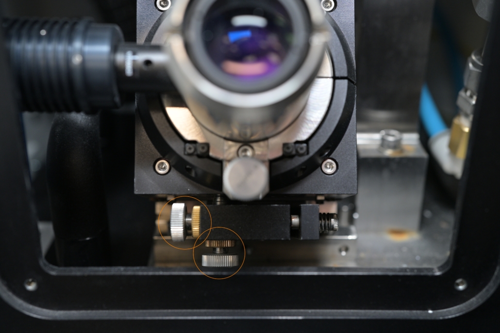
To do this you would have to open the door of the processing area and losen the 4 screws of the cover plate.
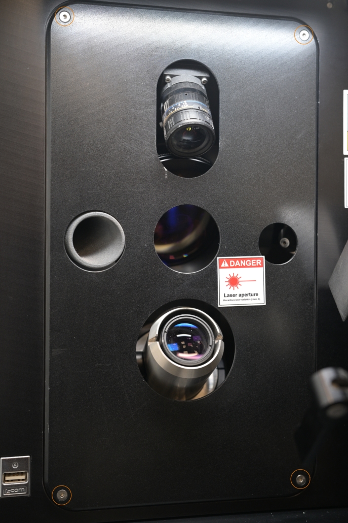
After removing the cover plate you would have to use the 2 marked screws to adjust the camera mechanically in x- and y-direction.

A good Eucentric adjustment determines the output of your processes by a large amount.
Similar to the Camera Laser Offset Adjustment it should be carried out on a regular basis. Unfortunately it is a litttle more complicated, but we are going to try to guide you through the adjustment as good as possible.
First of all you should place a piece of silicon on a stub and either on the manual, motorized or thinning stage. It is nevertheless most convenient to use the motorized stage.
To begin with the adjustment you navigate in the software to the general settings menu and click on “Eucentric”.
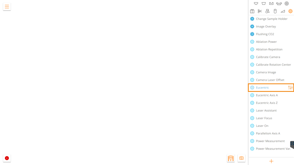
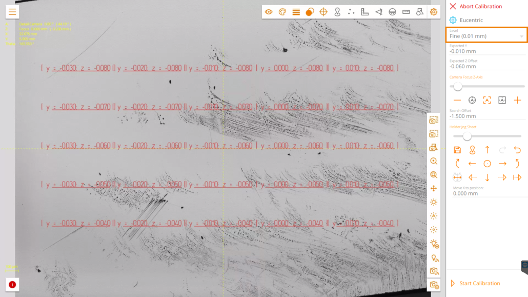
When you hit the start button you will be directed to the process overview screen. Now you can see the Eucentric overlay, showing different values depending on the chosen accuracy level (see the marked box in the next picture).
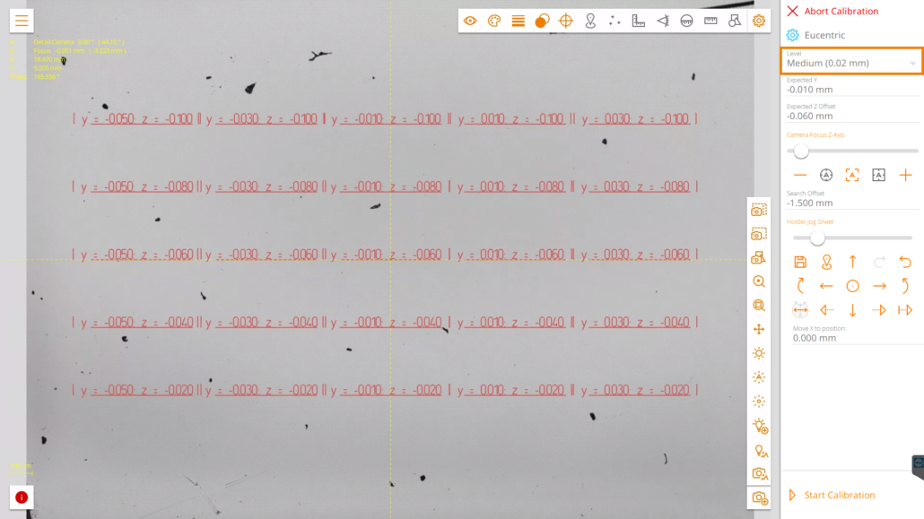
We recommend using the “medium” accuracy level to start the adjustment. The resulting grid will look something like this:
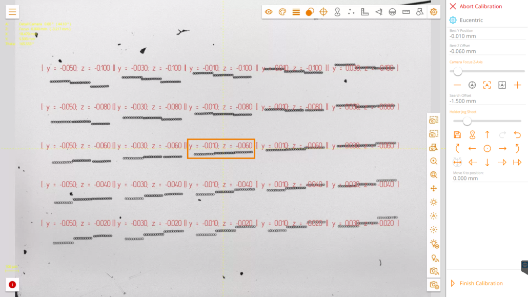
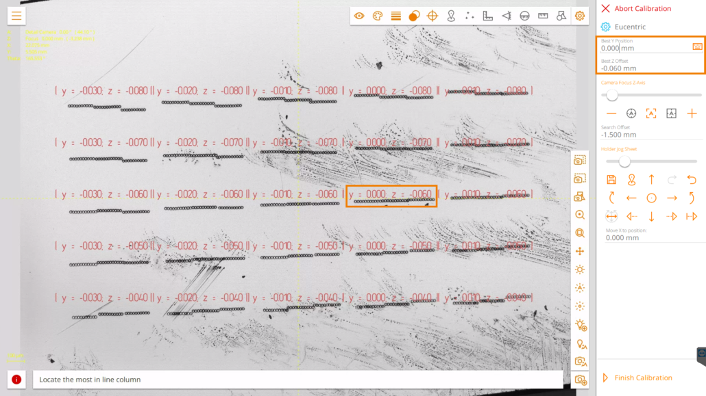
Now you need to look carefully for a triplet of lines that are closest to forming a straight line together (if there is any) or that are aligned as stairs. Note that your results may look different from our screenshot! We chose the values in the marked box to continue with the calibration. The values for y and z need to be entered in the boxes on the right side (Best Y Position; Best Z Offset). Then you hit “Finish Calibration” to save the adjustments.
In this case we will do the calibration again with the next accuracy level.
Again you have to look for the triplet of lines, that is closest to a straight line. If you found a triplet you can take the values and enter them as Best Y Position and Best Z Offset and finish the calibration.
This calibration can again be repeated with the next accuracy level to even determine more accurate values. The workflow stays the same.
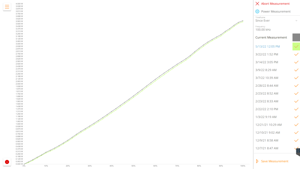
The Laser Power Measurement automatically measures the actual laser power in dependence of the attenuator position or the laser amplification power (depending on your system setup).
To carry it out you navigate in the software to the general settings menu. If you have a stage installed it is best to remove it via “Change Sample Holder”. Afterwards you select “Power Measurement” as shown below.
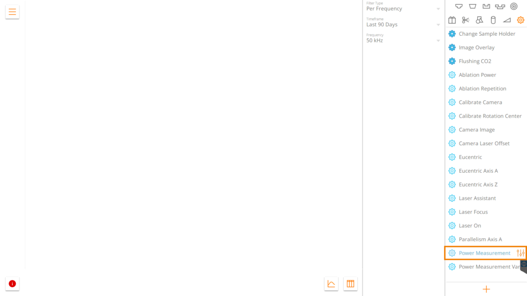
Now you could either navigate to the starting screen of the measurment when you click on the staring symbol (the three sliders), or you could view older measurements for comparison. Therefor you would want to set an according filter for the Timeframe and Frequency. Depending on your system setup, the measured curves might look different from the one below. The shown curve is from Laser Option 2.
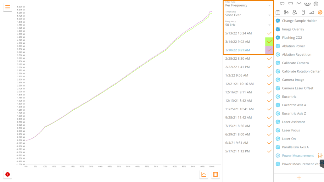
Before you start it is possible to add multiple frequencies to carry out a batch measurement. Or you could measure single frequencies.
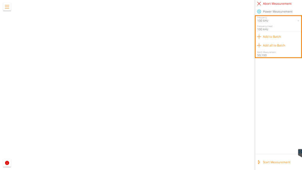
The process will take a few minutes and afterwards you are presented the new curve. Again it is possible to compare the new curve with older ones.
If everything is alright you can hit the “Save Measurement” button. If the curve looks totally off you might want to press “Abort Measurement” and carry it out again or contact your service representative.
